Day 72
Well another week has passed with little work to show but next week I should be building up quite a backlog of work to show off. In fact the goal is to write up a post for every day I'm off and work them through until I come to posting them so things should get a lot more coherent from here on out. The game plan starts on Friday which will see me finally finishing the clock circuit up then I will be moving on to other portions of the project and will be doing a full write up on each piece.
Wednesday, April 13, 2016
Thursday, April 7, 2016
A quick apology
Day 66
This is not a post in the real sense just an apology for no posts for 2 weeks now. Things remained somewhat difficult longer than I anticipated and then a science fair project came up for my son so I had to devote my free time to that. We will resume normal activity next Wednesday April 13th followed by what should be an exciting 2 weeks of posts as I will be off of work from Friday the 15th for a week and I am using that time to catch up on my various projects this being a major 1 of those.
This is not a post in the real sense just an apology for no posts for 2 weeks now. Things remained somewhat difficult longer than I anticipated and then a science fair project came up for my son so I had to devote my free time to that. We will resume normal activity next Wednesday April 13th followed by what should be an exciting 2 weeks of posts as I will be off of work from Friday the 15th for a week and I am using that time to catch up on my various projects this being a major 1 of those.
Saturday, March 26, 2016
Apologies, but no news today
Day 54
It has been a busy couple of days and my head hasn't really been in the game so no real post today but the announcement that I am in fact switching to 1 day a week posts from here on out Wednesday will be the day so. More to come then and I will be back on track. There is still an excitement in me about this project but I need to temper things to a slow burn to account for the duration this project will take. Wednesday we will be breaking down the machine language of professor Porter's design and my proposed changes to it. and from there likely a walk through of his control circuits.
It has been a busy couple of days and my head hasn't really been in the game so no real post today but the announcement that I am in fact switching to 1 day a week posts from here on out Wednesday will be the day so. More to come then and I will be back on track. There is still an excitement in me about this project but I need to temper things to a slow burn to account for the duration this project will take. Wednesday we will be breaking down the machine language of professor Porter's design and my proposed changes to it. and from there likely a walk through of his control circuits.
Wednesday, March 23, 2016
Finally the answer I've been seeking
Day 51
Finally I think I've hit on what I've been missing for the overall function of this machine. That is the good news, the bad news is it's the part even professor Porter says figure it out for yourself on with no real parachute. Oddly enough this fills me with excitement rather then dread.
The finite state machine feeds into the combinational logic which is what decodes the instruction from the memory to the necessary control lines and timing instructions to preform the proper sequences in order. This may be a limiting factor while I wrap my head around this but in the day or so I have been working through it I am already seeing how it will work and what it may require for the more advanced designs I'd like to include in my design. Essentially each instruction you want to include has to have it's own physical decoding this is straightforward enough but the trouble comes in with the added function codes I would like to add it may require an upgrade to a 16 bit instruction system.
This genuinely is the break I have been searching for years for the single key my little mind has refused to understand to break the barrier between what you want to do and what the how the computer determines what steps to take to accomplish that goal. It is also 1 of the primary missions of this project to truly grasp how we went from instructions to execution in a computer I am beyond excited about what this means and cannot wait to study this further. I will need several days to process what this means for this project in particular but I can see from here that it will make things fall into place much better I am already grasping the function of the finite state machine and all of its ancillary components much more fully now.
The instruction calls are based on 8 bit instructions that for obvious reasons cannot repeat. they are called in the order they were indexed based on a 16 bit memory address this address is usually incremented to the next instruction but there are several instructions which will either temporarily or permanently jump to a completely different instruction address. This system is overall nearly identical to the machine language of modern computers with some differences in execution. These 8 bit instructions are the limit to the bus size for my redesign the positive here is if I include the constant function separately like I want to then this will open up several new instruction sets as there is an instant instruction which is the same as a constant but instead of having the constant loaded from a register or switches it is loaded in as 5 bits of the instruction. The design of this instruction set will require quite a bit of work, checking and re checking to make sure there are no duplicates. If all else fails then I will have to move to a 16 bit data bus and expand the whole computer or rework the intire instruction system. Neither is out of the question though fully re working the instruction system would likely be much cheaper though not very fast as I would be starting from scratch in this lesser understood area with professor Porter's original design as only a road map. My mind is saying it may be cleaner and easier to build the instruction set up to a larger number of bits that will allow for not only a more robust instruction set but a slightly cleaner execution though only fiddling with this idea would be able to tell if it could lead to fewer physical components in the build.
I have also made a decision on the physical layout of my computer. The various sub assemblies will be housed similarly to the clock circuit. On their own boards or plexi inserts just like professor porters system but each module will plug into the backing plane with a physical connector which will allow for easy removal and repair of faulty modules. Though I do not foresee this having a high degree of usage I would still like to think of the poor servicing guy (me) when something does inevitably break or blow smoke on me. These modules will be attached to their faceplates and the faceplates will be cut to fit the area allotted them in the cabinet.
This is a short update because of these revelations but Saturday will be jam packed with information I am sure of that. I won't venture what direction I'm going to end up chasing this in yet. But we shall see then.
Saturday, March 19, 2016
Finite state machine is a tough nut to crack
Day 47
Professor Porter goes into great detail about how the finite state machine works and it's theory of operation. However he does not show a full blown schematic, but there is a layout in the various downloaded image files, for this vital portion of the computer. He somewhat seems to leave much of this area up to you to figure out. However, this is the some of the truly uncharted territory for me I understand the abstract of this system but cannot quite wrap my brain around the full function of this. I understand that it is essentially breaking out the clock pulses so that each individual pulse can control the specific portion of the computer it has to but the underlying control structure it orchestrates is eluding me for the moment. This lack of understanding is somewhat exacerbated by professor Porter's desire that those control systems be figured out by the student as well. This is an area I need to study more and shows that perhaps I should go back and try to better understand how all of these functions are executed. This is the plan starting with today's post.
So instead of killing myself by jumping around in the paper any further I am just going to mosey on from where I left off with the adder. This brings us to the zero detect circuit it's function is very simple it's use, however is not immediately apparent to my eye unless it can be used to call a halt or perhaps if factoring a number but I am not sure beyond those 2 cases hopefully it's need will be demonstrated in the future. The sign bit is discussed next and it is simply represented by the most significant bit on the bus this means that instead of a full 8 bit word we a technically only working with 7 bits for numbers and 1 bit for sign. This is actually somewhat confusing as you look through the paperwork as in some diagrams professor Porter has the sign bit broken out from the ALU output but in many of the block diagrams but in the reference materials and schematics it is nowhere to be seen so this is how I ended up drawing this conclusion. For the ALU functions this makes sense as any function performed on this bit to compare it to the sign bit on the other register will result the mathematically proper answer. the only issue with it I have is if a number carry's over to the 8th bit it will give an incorrect answer, but these kind of non error errors can be seen in many older systems and in the design history of several programming languages. It is simply misleading in various diagrams and the like.
The 3 to 8 decoder shown in professor Porter's design has been replaced in mine by the 4 to 16 design which is a simple extension of his principals. This is done to accommodate the added functions I would like to include in my build. So far we have added a right shift but I am considering adding a subtract function if it is plausible. Other considerations so far are a constant (not necessarily as part of the decoders function), A NOT function for the "C" register, a NAND function, and finally a potential multiplication function. As these ideas represent only 4 or 5 additions to the decoder they would be no problem for that end, the limiting factor will be my desire to expand the ALU and by extension the part count. This does leave me open to adding other functions that may use unused portions of the existing system or combining some functions like in the logic block. For instance the NOT "C" function or the NAND function could be incorporated into the existing logic block and as such would add very little overhead but almost all of the other functions will add to the parts count by at least 10 relays. If I attempt this less expensive single or double pole relays may find their way into the project. Many portions of this are still up in the air. Another modification I will be making to the decoder is the change of the "000" input going from ADD to "Not Used" this is a clearly stated flaw in professor Porter's design and 1 that I will build out of my design. the simple truth to this is that it takes no effort to send that "000" down the line which means that any time the system does not need the ALU to output then it needs only cut power from the decoder. The original design used "111" as the "Not Used" which meant that power to the decoder could not be cut unless you wanted to ADD.
Wednesday we will be talking about the overall system architecture as a warm up for breaking down those control systems and what they entail. I will be focusing on the various registers and what their functions are in the operation of the computer.
Wednesday, March 16, 2016
Adder unit, the end of the functions
Day 43
The adder is discussed in some detail in a few places but it's design is identical to that of Konrad Zuse from the 1941 relay computer he built. I have included a Fritzing diagram of the single bit and the full 8 bit chain in the Google Drive folder I have only done a screencap of the single bit as to zoom out enough to see the full chain of adders makes it virtually useless as an aid.
On top of the discussion in Harry's paper on the he also points us to a Java applet demonstrating the adders function. I have not jumped through the hoops necessary to get this to work on my computer as I keep Java on a very tight leash for security's sake, but it looks fascinating. Both give a decent rundown of the history of the adder though the Java page gives a bit more detail I will not attempt to mess with what seems to me so succinct and as such will be following Harry's lead and simply copying this full adder over to my design, which is even used in the RC2 design unaltered. The other function of this circuit is incrementing this function will take Bin and output a +1 to it instead of adding it to Cin this is accomplished by inputting a 1 to the Carry in on the 0 bit a a simple control circuit for these functions is shown in the RC2 plans and I will likely be basing my design on it.
This is the last of the functional portion of our design from here we get into the program counter and the memory and the various control circuits and putting all of these circuits together with those controls shows the 1 major flaw in this design besides speed. That is inefficiency the adder all of the logic functions and the shift operations all happen regardless of weather or not they are needed we simply select the 1 we want to go out onto the bus this design while simple is very inefficient in power consumption and in the lack of ability to multitask. In modern computers these functions can all be happening to different sets of numbers simultaneously or nearly as such. this is called multi-threading and it drastically helps to increase speed of computing as it means 2 or more calculations are happening at 1 time, which effectively doubles, triples, or quadruples output speeds. This effect could be performed in our design but it would come at the cost of greatly increased complexity and cost several new registers would need to be added to the design to store the numbers as well as a drastic overhaul of the control and mode selection system and the addition of at least 1 more bus or a widening of the existing bus. While these changes would be fun to make and I am not throwing them aside for a long term project the lack of real world use cases for this device limit even my desire to chase that rabbit. For now I think this system will suffice for my purposes.
Next I do believe some design and discussion on the finite state machine will be in order. This will start giving structure to the underlying control systems we will be building in later. Then after or during that we will start our mock ups of the various portions of the system we have already discussed. I am working on a build up board design to make the build ups go more smoothly and allow us to see each circuit in detail.
Saturday, March 12, 2016
Explaining motives in depth
Day 39
Ok first an apology for the massive divergence but I think it's a necessary one. A few program notes before I get to the meat and potatoes of this post.I am breaking things down a bit I have a few other ideas I want to get started on that don't involve this project and as such I'm cutting out the Monday posts to this blog. The aim here is to educate and explain and the pressure of 3 posts a week for a project setup to be this long term is a hard self goal so we're going to try 2 a week for a while and see if that not only improves quality but coherence of things. So from now on Wednesday and Saturday for posts and hopefully a new announcement soon. On the physical build the clock circuit will be finished soon but after it is finished I have a Christmas gift I should have finished first to get back to then after that is done we will resume with the various test builds.
As an explanation for this post I was chatting with my girlfriend the other night about this particular project and I was asked about not only the function of this computer but the purpose and use for it as well. The 2 answers kind of go hand in hand so I'm going to attempt to break it all down in this 1 post.
I am an unabashed geek there is no denying it and I wouldn't dare insult anyone's intellect by trying to. This fact leads to several assumptions some right and some not so much. First I love tech and all of it's many forms I have an intrinsic knowledge of how electronics function this makes me a superb troubleshooter. Unfortunately it tends to lend credence to people thinking I know how these things work on a deep level, I do not, usually. When it comes to computers especially I am quite knowledgeable about how the OS works and how to sort out problems like that as well, I also have the aforementioned tech skill which helps find physical issues quickly. These 2 skills make for a great repair man but that does not require a knowledge of how a PC thinks and preforms it's functions. More importantly given the way my brain works this lack of understanding leads to a disconnect between the hardware of the computer and it's software. I get the abstract of it all but when I try to apply this knowledge nothing makes sense and I quickly lose patience with the situation. I have broken down much of this project into parts that I understand fully, parts I half get, and parts I am completely lost on. The only parts I'm completely lost on are the actual programming of this beast the physical parts all make at least some level of sense and I am 100% certain will all make total sense once I take the time to break them down and model them. So goal #1 is to better understand how modern computers work and use that knowledge to boost my ability to code and problem solve for the machine.
Goal #2 goes back to the unabashed geek thing I love tech and historical tech like this relay computer or the PDP-8 from DEC or even the DOS like DEC system I work with at work is utterly fascinating. The relay computer is not the first computer ever built but it was an important milestone in the road to the transistor and also within reach of a hobbyist such as myself affording and building. Relays are readily available and are largely unchanged in function if not design from that time, this means that any computer I build in this manner will be very similar to what came before. Historically speaking while this uses no semiconductors or any of their direct precedents (Vacuum tubes)it still functions in nearly the same manner as a modern PC's processor. The series of registers and functions are all largely unchanged in ability though the scale is simultaneously much larger and much smaller. So goal #2 is simply to have built a piece of history.
Goal #3 is short and sweet. This is a project to do with my kids who have both shown at least a mild interest in the topic. The knowledge they gain from this can easily help them in their lives from a better understanding of mathematics to problem solving to an early exposure to real engineering. Plus they can make it make lots of noise. That's about it for goals, there are more but they're minor.
Now as for a purpose for this computer that's a bit more abstract as it cannot do things a modern PC can. What it can do is math and in a consistent and loud manner. So doesn't this make it a glorified calculator? Why yes, yes it does just like your iPhone or DROID or Dell. The difference is in the learning and teaching ability with this glorified calculator. Not only am I learning something but see goal #3. This machine can be rolled out for whatever special occasion calls for it or more likely will simply become 1 of my trophy's of geekdom. It will likely be stored until I get a place of my own and then it will be placed on display wherever I put things like that. It can be programmed to preform many complex functions but really any everyday use of it is impractical and as such any question about it's use is like asking for an explanation as to why children play. There is no point or use beyond the education of it.
Now that I have that out of the way we can get to the explanation of what this all does. Obviously this is a computer but not like what many people carry around or have sitting in their homes. This was before programming languages made it easy to preform complex multi step functions with just a few words. This is like trying to use a modern computer without the mother board, monitor, keyboard, and mouse. The computer I am building here is what functionally happens all on the CPU's chipset in a modern PC. Most people have experience typing things into a computer and getting information back but the part they miss is loads of other people spent boatloads of time making the system work that way. Essentially a modern computer is a translator for a translator for the CPU and you to communicate. Most programs break your inputs like mouse clicks and keystrokes into some type of bytecode this is a numerical representation of what you are requesting the kernel of the processor turns that bytecode into the logical 1's and 0's the CPU can actually work with.
Those 1's and 0's are what we are working with in the relay computer. Instead of having a program put those 1's and 0's in for us we put them in manually using switches. The switches help us preload the computer with everything it needs from the instructions to preform the program to the starting inputs of the program itself. these inputs are made with the clock off and it is either manually cycled to allow for the next input or set to run to allow the computer begin its automated calculation of whatever program was inputted. This whole process is done either automatically by modern computers or prewritten by the program designers. In the case of prewritten instructions they are usually written in some higher programming language like C++ or Java which then has to be compiled into bytecode that the CPU can then translate into the instructions for the CPU to preform. This double translation is done to make programming more accessible the higher languages are more human readable and allows us to succinctly preform complex calculations. Some programmers write in machine language which is essentially talking directly to the kernel, this has a few advantages. First super lightweight code machine language has virtually no overhead and as such it is really easy to drastically reduce file size. Also it tends to run much faster. The downsides are that it is truly difficult to master comparatively to other languages. It is also so powerful that small mistakes can cause massive problems from system crashes to security vulnerabilities. It is also highly specific to the system it is on while Java can be compiled for a Mac or PC or Android without trouble each has its own machine language to be learned. We will be working with our own machine language for this build as the instruction set will be used to directly interface with the various functions we can preform.
I hope this has been as enlightening to you as it has been clarifying to me in where we are and where we are headed.
Wednesday, March 9, 2016
ALU logic functions
Day 36
Today we'll be breaking down the logic block of the ALU, but first a word on the build I still haven't gotten the clock finished though not due to any real difficulty other than a lack of time. should be getting it finished soon but no distinct timeline as of yet.
The logic block contains 2 inputs in the form of the B & C registers and preforms several functions on those inputs simultaneously the only thing that determines what is gated onto the bus is the enable circuits for each function. each bit of the logic block contains 2 relays using a total of 16 relays to preform the NOT "B", AND, OR , and XOR functions. There is an unused switch in the logic block and I may put it to use as a NOT "C" function to further reduce cycle counts for functions that may need to NOT 2 numbers back to back, but I am unsure if it has any real benefit yet so for now it is tabled.
The NOT function takes the input from the B register which is
inputted to the coil and simply outputs the opposite. Thus if B is high
it energizes the coil drawing the contact away from the NOT output
forcing it LOW but if B is low the coil gets no power and the switch
passes a voltage or HIGH signal through to the output.
The AND function takes the inputs of B & C and only goes high when both are high. the ingenious part of this circuit is that the B side is drawn from the N/O contact from the NOT switch then put into the N/O of S1 on the C relay and the common of S1 is fed as the output of the AND function.
The OR function takes B & C and will read high if either of them or both of them are high. It's operation is simply taking the N/O contact on 1 switch for each input and combining them into a single output.
The XOR function is the last of the functions from Harry Porters design it is similar to the OR function with the exception that it will read low if both inputs are high. This function is accomplished by taking the N/O of a switch on B and connecting it to the N/C of a C switch and the N/C from B to the N/O on C this means if either relay is energized a path from the V supply on the B switch will lead to the output but if both are high then it will break the connection.
The 2 switches that are left may remain that way but between the NOT "C" function and possibly adding a NAND function I have a feeling they will get used up at least partially. The NAND would be the priority as NAND gates can be used in a multitude of different ways and would afford whole new functionalities.
Today we'll be breaking down the logic block of the ALU, but first a word on the build I still haven't gotten the clock finished though not due to any real difficulty other than a lack of time. should be getting it finished soon but no distinct timeline as of yet.
The logic block contains 2 inputs in the form of the B & C registers and preforms several functions on those inputs simultaneously the only thing that determines what is gated onto the bus is the enable circuits for each function. each bit of the logic block contains 2 relays using a total of 16 relays to preform the NOT "B", AND, OR , and XOR functions. There is an unused switch in the logic block and I may put it to use as a NOT "C" function to further reduce cycle counts for functions that may need to NOT 2 numbers back to back, but I am unsure if it has any real benefit yet so for now it is tabled.
 |
| Not Function |
 | |
| AND Function |
 |
| OR Function |
The OR function takes B & C and will read high if either of them or both of them are high. It's operation is simply taking the N/O contact on 1 switch for each input and combining them into a single output.
 |
| XOR and completed logic block |
The XOR function is the last of the functions from Harry Porters design it is similar to the OR function with the exception that it will read low if both inputs are high. This function is accomplished by taking the N/O of a switch on B and connecting it to the N/C of a C switch and the N/C from B to the N/O on C this means if either relay is energized a path from the V supply on the B switch will lead to the output but if both are high then it will break the connection.
The 2 switches that are left may remain that way but between the NOT "C" function and possibly adding a NAND function I have a feeling they will get used up at least partially. The NAND would be the priority as NAND gates can be used in a multitude of different ways and would afford whole new functionalities.
Monday, March 7, 2016
Test rig and Clock
Day 34

The clock circuit build will be finished tonight I discussed the exact physical layout with several people and the decision was completely unanimous so I have decided that instead of simply prototyping this out it will be built as a permanent fixture. This decision was predicated by the cap packs and the trouble I had with them the other night. When I soldered them to the perfboard, the way things worked out they left more than ample room for the relays to fit in as well as the switches and indicators. This allows the clock circuit to not only look cohesive in the final build but grants us the ability to use it during other phases of prototyping and testing apart from the other sub assemblies themselves.
 Each pack is connected on the vertical plane leaving a sizable space below or above for the relays to be fitted. To secure the relays I am leaning towards cutting a hole large enough for the base of the relay to fit into and hot gluing them in place then wiring everything up on the underside the switches will be simple slide switches mounted through the board for now but for the final build they will be removed and replaced with toggle switches for the run/stop and power switches and a momentary toggle for the single step switch which will be extended through the Plexiglas cover plate.
I will likely post videos of the clock and test rig in action tonight and will discuss the clock at length Wed. after that we will move on to the next portion of our build which will be the various functions of the ALU. Then a move back to theory of operation as I seek to add functions to the computer to fill up spots in my 4 to 16 decoder line.
1 of the most important parts of building any physically complex machine like this is to make sure all the parts work not only together but individually. That is by far a much easier task with a build this big if you test your components first. In industry this is simple quality control in our case it will save hours of troubleshooting and hair pulling. so today I threw together a quick test rig for the relays which doesn't need to be overly complicated in this case it consists of 5 indicator LED's and a switch attached to a relay socket you simply plug the relay into the socket and 4 of the LED's should light flip the switch and all 5 should be lit then remove the relay and insert the next relay. This test should take less than 10 seconds per relay from start to finish which should allow for quick and efficient testing of the over 500 relays involved in this build. This is 1 way to skin this cat in all honestly it could just as easily be accomplished by running each relay as R1 in the clock circuit but this would induce many other points of failure but would give the benefit of a more realistic load to test on. In this case with how basic a component these relays are there is something to be said about following K.I.S.S. Which is a principal I try to live by. you could also build many other test rigs that would all work and all would likely accomplish the same basic task. The long and short of it is as always there is more than 1 way to skin a cat. MEOW!

The clock circuit build will be finished tonight I discussed the exact physical layout with several people and the decision was completely unanimous so I have decided that instead of simply prototyping this out it will be built as a permanent fixture. This decision was predicated by the cap packs and the trouble I had with them the other night. When I soldered them to the perfboard, the way things worked out they left more than ample room for the relays to fit in as well as the switches and indicators. This allows the clock circuit to not only look cohesive in the final build but grants us the ability to use it during other phases of prototyping and testing apart from the other sub assemblies themselves.

I will likely post videos of the clock and test rig in action tonight and will discuss the clock at length Wed. after that we will move on to the next portion of our build which will be the various functions of the ALU. Then a move back to theory of operation as I seek to add functions to the computer to fill up spots in my 4 to 16 decoder line.
Saturday, March 5, 2016
Physical breakdown and parts ponderance
Day 32
Well over a month in and finally some action I received the first 10 relay order Thursday and the 80 relay order form earlier this week Friday. So mental note. Fewer. Bigger. Orders. these coupled with the parts I already have and a quick trip to Radio Shack for some wire and quick and dirty switches has me poised to start building. The kids and I sat down to start work and 2 things became immediately clear 1 they wanted to know how it all worked in detail as bad as I did (good thing). 2 I have no idea how HP put those capacitors together the way he did because those leads leave no room for error with placement. Even with 2 sets of hands manning the iron and holding/positioning them just assembling 1 pack of 5 caps took the better part of 30 minutes.

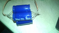
Now I can be tenacious but I can smell wasted time in this not to mention the fact that I didn't much trust those craptastic connections so I grabbed a large perfboard I had laying around as a spare from my arduino LED cube build. here is the link for the perfboard. So the game plan for today is to desolder those caps then mount each pack in a corner of the perfboard and work with them there. The question then becomes weather to mount the whole clock circuit like that or to leave the relays off the board and mount them similarly to the rest of the computer. I think either way mounting the capacitors like this will neaten things up nicely which is always a good thing.
Let's take a look at the physical relay's themselves as they're kind of neat. As you can see in the pictures the relays aren't overly large they measure about an inch and a half high 3/4 of an inch wide and 1 inch long there are a total of 14 pins on the bottom which are blade style for insertion into a socket and have a hole in the blade for easy solder application should that be the case. In our case I will be doing all of the prototyping with sockets for ease of assembly and testing purposes as well as building a nice test assembly for quick and easy pre installation testing. In the pictures I've included my watch for scale as the pictures included in the HP computer materials was a little hard on scale for me. Internally the relay is quite a marvel of efficient packaging and even includes an LED on the coil to indicate when it is
energized which should add a whole other dimension of blinky blinky to our build. It does give the benefit of potentially removing some indicators throughout the build and my first thought is to rid myself of the indicators for the clock circuit overall.
 The following pictures are labeled to show the individual sections on each relay. the full images of these are in the google doc as well as a few others that I took and left unlabeled. Once the clock is put together I will likely post a short video of it in action.
At this point we haven't had time to get much built and with the sockets coming not much will likely get built for a few more days but the capacitor packs will be getting assembled and the wiring planned I will also be working on the test rig and will post a schematic of that soon. On orders I looked deeper into the power supplies used in the HP computer and he uses a now defunct Radio Shack model that was a 13.8VDC 10 A CB radio supply a brief search through amazon found similar here. The supply is at the heart of this build and Harry Porter used 2 of these 10 A supplies and I will be as well though for the time being I have only ordered 1 for testing and prototyping. Originally I had planned on using an old computer power supply for the ease of adding a 5V line for the memory chip circuit. That plan may still be put to use as I have an 850W Corsair supply that should supply more than enough power for the whole shebang.
I know today was a big deviation from the theory of late but the physical components are what this will ultimately be about and as much time will be spent on that as on the understanding and planning of the operation of this computer. Monday will likely cover in depth the operation of the finished clock circuit. Likely with lots of build pictures and hopefully a video of it running too.
Well over a month in and finally some action I received the first 10 relay order Thursday and the 80 relay order form earlier this week Friday. So mental note. Fewer. Bigger. Orders. these coupled with the parts I already have and a quick trip to Radio Shack for some wire and quick and dirty switches has me poised to start building. The kids and I sat down to start work and 2 things became immediately clear 1 they wanted to know how it all worked in detail as bad as I did (good thing). 2 I have no idea how HP put those capacitors together the way he did because those leads leave no room for error with placement. Even with 2 sets of hands manning the iron and holding/positioning them just assembling 1 pack of 5 caps took the better part of 30 minutes.


Now I can be tenacious but I can smell wasted time in this not to mention the fact that I didn't much trust those craptastic connections so I grabbed a large perfboard I had laying around as a spare from my arduino LED cube build. here is the link for the perfboard. So the game plan for today is to desolder those caps then mount each pack in a corner of the perfboard and work with them there. The question then becomes weather to mount the whole clock circuit like that or to leave the relays off the board and mount them similarly to the rest of the computer. I think either way mounting the capacitors like this will neaten things up nicely which is always a good thing.
 |
| MY4 12DC coil 4PDT relay |
 |
| MY4 12DC coil 4PDT relay |
Let's take a look at the physical relay's themselves as they're kind of neat. As you can see in the pictures the relays aren't overly large they measure about an inch and a half high 3/4 of an inch wide and 1 inch long there are a total of 14 pins on the bottom which are blade style for insertion into a socket and have a hole in the blade for easy solder application should that be the case. In our case I will be doing all of the prototyping with sockets for ease of assembly and testing purposes as well as building a nice test assembly for quick and easy pre installation testing. In the pictures I've included my watch for scale as the pictures included in the HP computer materials was a little hard on scale for me. Internally the relay is quite a marvel of efficient packaging and even includes an LED on the coil to indicate when it is
energized which should add a whole other dimension of blinky blinky to our build. It does give the benefit of potentially removing some indicators throughout the build and my first thought is to rid myself of the indicators for the clock circuit overall.

 The following pictures are labeled to show the individual sections on each relay. the full images of these are in the google doc as well as a few others that I took and left unlabeled. Once the clock is put together I will likely post a short video of it in action.
At this point we haven't had time to get much built and with the sockets coming not much will likely get built for a few more days but the capacitor packs will be getting assembled and the wiring planned I will also be working on the test rig and will post a schematic of that soon. On orders I looked deeper into the power supplies used in the HP computer and he uses a now defunct Radio Shack model that was a 13.8VDC 10 A CB radio supply a brief search through amazon found similar here. The supply is at the heart of this build and Harry Porter used 2 of these 10 A supplies and I will be as well though for the time being I have only ordered 1 for testing and prototyping. Originally I had planned on using an old computer power supply for the ease of adding a 5V line for the memory chip circuit. That plan may still be put to use as I have an 850W Corsair supply that should supply more than enough power for the whole shebang.
I know today was a big deviation from the theory of late but the physical components are what this will ultimately be about and as much time will be spent on that as on the understanding and planning of the operation of this computer. Monday will likely cover in depth the operation of the finished clock circuit. Likely with lots of build pictures and hopefully a video of it running too.
Wednesday, March 2, 2016
Adding a right shift register
Day 29
I am considering adding constant and circular shift right to my function set this will mean adding some complexity to the 3-8 decoder as it would then need at least 11 total outputs but adding 1 more bit to the input line will give me up to 16 total instructions so I am thinking on more instructions to add to make this change worth the effort. The constant would add another memory register but could be completely switch operated to save components, more on that Saturday.
The right shift function itself could be easily called by inserting a pair of relays into the left shift data stream before the shift and when enabled would simply reverse the order of the inputs. If you look at the schematic below it shows how I plan to implement this shift though the tagging makes it somewhat obfuscated. The b register inputs are on the right where they pass through the right shift enable circuit if the circuit is not enabled the NC contacts pass through the inputs in descending order where the most significant bit is shifted to the least significant spot and all others move up 1 place. If the relays are energized the order of inputs is reversed Shifting the least significant bit to the most significant place and all others moving down 1 place. The resulting outputs are placed into the left shift enable where if left shift is enabled then the bits simply pass through, if not the outputs are inverted again to match the data bus order. After this the resulting output will then have to go through yet another enable circuit that activates for either a left OR a right shift and a simple OR function will be added to the enable circuit to allow this and prevent feedback into the data bus.
 While this circuit adds 5 more relays minimum to the overall design I feel it also adds extra functionality that will save valuable compute cycles and saves the need for yet another data line set in this already large computer. the indicator lights will be placed at the input to the shift enable circuit to save the need for 8 extra lights. There will be either 1 or 2 lights to indicate which shift function is being called. I am as yet unsure if this will be a bi color LED, 2 separate indicators, or 1 indicator that is on for 1 shift or off for the other. That is a style call though so it can wait quite some time. I will be prototyping this circuit up ASAP.
Parts update, still no sign of anything from china but my capacitors and the first batch of indicators is out for delivery today. I also received shipping notification on the second larger batch of relays I ordered over the weekend so those should be here in a few weeks. I ended up making my purchase decision based on both the size of this order and the resultant per unit cost, fingers crossed it works out because that was quite a few relays. It did manage to get me below $2.50 each relay so I think I may try and do larger batch orders like that from now on.
I am considering adding constant and circular shift right to my function set this will mean adding some complexity to the 3-8 decoder as it would then need at least 11 total outputs but adding 1 more bit to the input line will give me up to 16 total instructions so I am thinking on more instructions to add to make this change worth the effort. The constant would add another memory register but could be completely switch operated to save components, more on that Saturday.
The right shift function itself could be easily called by inserting a pair of relays into the left shift data stream before the shift and when enabled would simply reverse the order of the inputs. If you look at the schematic below it shows how I plan to implement this shift though the tagging makes it somewhat obfuscated. The b register inputs are on the right where they pass through the right shift enable circuit if the circuit is not enabled the NC contacts pass through the inputs in descending order where the most significant bit is shifted to the least significant spot and all others move up 1 place. If the relays are energized the order of inputs is reversed Shifting the least significant bit to the most significant place and all others moving down 1 place. The resulting outputs are placed into the left shift enable where if left shift is enabled then the bits simply pass through, if not the outputs are inverted again to match the data bus order. After this the resulting output will then have to go through yet another enable circuit that activates for either a left OR a right shift and a simple OR function will be added to the enable circuit to allow this and prevent feedback into the data bus.

Parts update, still no sign of anything from china but my capacitors and the first batch of indicators is out for delivery today. I also received shipping notification on the second larger batch of relays I ordered over the weekend so those should be here in a few weeks. I ended up making my purchase decision based on both the size of this order and the resultant per unit cost, fingers crossed it works out because that was quite a few relays. It did manage to get me below $2.50 each relay so I think I may try and do larger batch orders like that from now on.
Monday, February 29, 2016
Clock update and Hodge podge
Day 27
 In case you have not looked over the contents of the Google drive folder I posted here is the clock circuit diagram. Looking it over in this form as opposed to in any of the HP drawings seems a bit more sensible to me. Most likely due to my having drawn it out. Operation of the single step is becoming more clear now and the overall function is starting to take shape in my head. This bodes well for when the circuit is built as it will likely reveal what is left for me to find in it.
Looking over the HP computer papers 1 theme is always present, control is up to you to figure out and while I intend to do just that the RC2 design shows many of these control mechanisms plainly. In the full adder of the ALU's the logical function of the increment function is described but not shown the RC2 goes into full detail as to how this is accomplished. As an amendment to my post from 27 Feb the logic block of the RC2 is much less robust that the HP computer as it can only AND, and NOT while the HP computer adds OR and XOR this is a severe speed limitation as OR and XOR are important functions however it only pays a speed penalty as with the AND and NOT you essentially have a NAND gate and NAND can be chained to create any of the other functions, so the ONLY penalty is speed. Speed is a penalty that can be paid easily with the RC2 as so many of it's other features add so much more speed to the system this also has the added benefit of reducing the number of enable circuits in the computer which while not much of a reduction in parts is still something to consider. More differential notes on the RC2 show that a single relay clock circuit was used instead of the larger but more stable HP clock. The finite state machine in each appears to be capable of 24 steps though the reset circuitry is different and the RC2 uses a 12 count with a prime count for each step more will come on that soon though as I believe the finite state machine will be the next prototype I build after the clock and at least 1 bit of the ALU, time will tell.
One thing I am starting to see is that while these 2 computers are drastically different, these differences mask the overwhelming number of similarities. Both authors are extremely competent and very efficient and I think that explains why even the differences are similar in many ways, I intend to leverage this as the HP papers show little of the control circuitry but the RC2 shows much of it but glosses over the more in depth explanations of the functional bits. Combining these 2 works and modifying things here and there will allow for potentially the efficient and true design I desire.
A further note on parts this week I ordered my second shipment of relays as well as the capacitors for the clock, 50 switches, and 20 indicator LED's this puts me in a good place for prototyping once they all arrive within a few weeks. These orders with the first batch which I'm still anxiously awaiting will allow for up to the full ALU and clock to be built and possibly the finite state machine.
Saturday, February 27, 2016
RC2 ALU
Day 25
The Largest departure between the HP and RC2 computers is definitely in the ALU itself the RC2 has a much larger instruction set and can carry out several more base functions as such this all adds to the overall complexity of the design but also helps to drastically improve functionality. What the HP can complete in a dozen clock cycles the RC2 can complete in 6 or fewer depending on the particular functions. This example is a perfect showcase for the evolution of modern computing and Moore's law in action using more modern techniques and customized components not only did the speed increase greatly but so did the complexity and usability.
The HP computer ALU consists of a full adder a logic block an incrementer and a left shift register but not much else. The RC2 has all the same functions but can carry out functions such as NOT or SHIFT on both registers not just 1 also the SHIFT functions go either right or left which drastically reduces cycle count in the case of a RIGHT SHIFT. The SHIFT can also be manually selected between circular or non-circular shifts. The RC2 also features a CONSTANT function that as of yet I have not seen in the HP computer but would drastically assist with reducing cycles and memory accessing.
I intend to spend some time studying the texts on both more in depth tomorrow and ferreting out more of the differences and to see what if any modifications I may wish to start designing into my build. Monday, however, I intend to move back to the clock circuit and walk through its operation with the schematic I drew up. Wednesday we will return to the RC2 build and what we can learn from it.
Wednesday, February 24, 2016
Schematics
Big news I finally finished the first of the schematics involved. I have setup a google drive folder with the .fzz file and screen cap of the schematic I will be adding more soon but the Clock circuit is up and having worked it out on Fritzing has helped immensely with my understanding of things. As soon as the first shipment of relays arrives this will definitely be the first prototype circuit that gets built many pics to come with that also. Many more to come soon. The game plan with these schematics will be to begin by drawing out the schematics provided in Harry's literature and other materials after that it will be left for me to modify each section as needed the various component parts will have interconnect diagrams drawn up then an overall block diagram will be built to guide the actual final assembly when the time arrives. This folder will also house all of the still shots of the build as it goes any videos will be posted to youtube.
RC2 returns for a comparison.
Day 22
Today we will be looking at the ALU in some depth but with a focus on the differences between the ALU logic in Harry porters computer and the Relay Computer Two. On the surface they have many similarities however the differences begin with component selection Harry uses a 12V ice cube type 4PDT relays while RC2 uses both 4PDT and SPDT relays with much lower power capability. While this is a small difference it is the first of many that allow for a much smaller, faster and more robust CPU, however it comes at the cost of needing much more in the way of support materials and memory. while this is a better representation of a modern CPU it does little to showcase the beautiful simplicity of the original designs of the 40's, though, that is not the purpose with RC2. In the case of the Harry Porter computer or my own the focus is instead on the theory and functional operation without thought given to speed or complexity but instead to understandability.
I am going to spend some time breaking down these differences as I see them and where they each have strength and weakness. To start with the ALU itself. First looking at the registers instead of using a pair of NOT gates to time out the delay between the LOAD and SELECT commands allowing for the HOLD line to be powered or cleared as needed RC2 uses a single SPDT relay and a 10uF capacitor to do a similar job given the power needs of the smaller relays this is potentially more effective and definitely more simplistic. However, it comes with the disadvantage of time in the larger relays of the HP computer as these relays consume more power even if at a lower voltage therefore this design lacks scalability while the HP design will work for even the smaller components.
A word on my comparison, I think both of these computers are utterly fascinating Harry's computer is a great teaching and demonstration aid and showcases the old school power that computers had while the RC2 shows just how complex and amazingly fast they are capable of being. so throughout this comparison do not get the impression that I don't appreciate the RC2 or think it inferior. It is just different and not the direction I am going. The RC2 is amazing and the goal of loading windows with it is quite lofty and rather neat and I'm intrigued and will be reading much more extensively on it but it is not quite my goal so don't judge it or me to harshly on that.
Monday, February 22, 2016
Functional Operation
Day 20
Today I finally got some work going on Fritzing and hope to have those files to share later this week and between that and the anticipated arrival of the first shipments of relays should be able to get back to work on the details of the clock circuit. For today, though, I will be focusing not on any specific circuit but on the operation of the overall system as I understand it to this point.
The overall function of this computer starts with a program being inputted by hand byte by byte via the 8 bit data bus. At the same time an address is assigned to the instruction being entered on the 16 bit address bus. once the program is entered into memory the initial value can be loaded onto registers as needed and then the clock circuit is unfrozen and the program is allowed to run in sequence until either a halt function is called or the clock circuit is refrozen. Arithmetic functions are loaded onto the B and C registers the result of this function is loaded back onto the data bus and inputted to whichever register needs it next then the increment register will signal to load the next instruction which will repeat the process. There are several registers on besides the B and C registers each has a specific function which almost all involve storage for a time for 1 reason or another. Registers such as the M1 and M2 or J1 and J2 or X and Y registers can also access the 16 bit address bus and in the case of M and XY they can load data onto the data bus as well J can only read from the data bus there is an incrementing circuit feeding into the Program counter solely for the purpose of advancing the program instruction set. While there are several other details such as control lines they add little to the discussion of the overall function of the computer.
Wednesday we will be going into more depth with the function of the ALU even more so than before and with any luck schematics will be forthcoming as well.
As a note on the Fritzing work I am still looking into building a set of custom parts but for the moment I have decided to go with individual discreet components. This will work in the short term for getting schematics drawn up and shared and will be refined as time goes on. So for the now my relays are made up of a coil and 4 SPDT switches simply laid out to resemble a relay of the type I desire which will work quite well for schematic visualization but will not allow us to leverage the full power of the Fritzing platform though for a project of this scale I suppose AutoCAD would be better suited for the rest of the layout types. If you haven't used Fritzing for a smaller project I highly recommend it as it will allow you to take a breadboard project and pull a schematic and PCB layout out of it with minimal work or take a schematic and prototype it well. It is a powerful tool that is free and rather well built.
Saturday, February 20, 2016
Not Quite The Clock Circuit As I Had Planned
Day 18
This was supposed to be an in depth look into the clock circuit but I'm reading through the material and looking over the schematics and redrawing them myself and I'm just not seeing it yet hopefully later this week I can come back to it when the relays arrive and I can build it and see it in action. This actually seems to be a problem I will be running into a lot with the hand drawn schematic photos Harry supplies on the website. I am trying to hand redraw them into a form factor more to my thinking but would prefer to get them up on Fritzing asap so I can look them over in greater detail. I also think all of these circuits will be better understood oncee they are broken down and built in the physical realm.
Problems with my sleep deprived brain aside, on the physical layout of the cabinets. Harry's design is constructed of 4 cabinets I intend to split off the Memory module to its own cabinet to allow for further expansion of the computer but more to give space to a less modern and more period appropriate form of memory in the future as well this major modification will be baked into my design but will be performed as an upgrade not part of the initial build. I am also considering adding a permanent storage form to store whole programs but that will be a considerable add on in the future but will greatly add to the functionality of the overall system.
Well today's post was something of a softball but I promise back to the salt mines on Monday where hopefully I can get back to the clock otherwise we'll be on to the next part.
Wednesday, February 17, 2016
The clock circuit (Basics)
Day 15
Shipping notification has been sent on 10 of the relays I have on order hopefully I will have them in hand within a week and a half. Just in time for the next order to be placed, hopefully the other set arrives by then as well so I can make a full decision as to which supplier to use.
At the outset the clock looked to be 1 of the simplest sections of this build having now delved into many of the various pieces and seeing how the clock will need to behave I have the feeling this is a much bigger portion than first glance will tell. The basics of the clock is a simple recursive chain of 4 relays with capacitors in between to add a slight delay and allow the clock to pulse fully at any given moment 2 of the relays are on and as such we can derive a square wave using a simple Boolean expression. The big trouble comes in when you understand that this clock needs to be started and stopped in such a way as to not give errant pulses and also needs to be able to be single stepped through it's various states this adds a level of complexity not initially seen. I think this will be broken up into several days of chasing down answers.
For today we will focus on the 4 main relays and their capacitors The 4 relays are labeled "A" "B" "C" and "D" each coil is attached to the capacitor and the normally open contact on 1 of the prior relay's switches A to D, B to A, C to B, and D to C the common contact of that switch is connected to the normally closed contact of a different switch on the prior relay, the common of which is connected to voltage. This means that once the circuit is set to running it will continue to run indefinitely without any assistance from us. However it also means we cannot control it without using some control circuitry. Which we will begin to breakdown in Saturdays post.
On the physical end this basic clock has only 8 schematic parts which are actually made up of 24 discreet parts the 500uF capacitors used are actually 5 100uF caps wired in parallel the part Harry uses is a non polarized style and is the exact piece I intend to use as well. It is from www.allelectronics.com part number is NC-100. I intend to list in a separate post in the future what and where I sourced all parts from so they can be easily found from a single page but I will also continue to discuss them in their related posts.
Monday, February 15, 2016
Register Storage
Day 13
I am having a lot of fun getting lost in the minutia of this build and there are a lot of little nuances to it to get lost in but the real story is how all of this relates to the architecture of modern computing. While the components have changed, shrunk, and sped up significantly the basic functions of those components has not changed. The transistors on a modern CPU act in the same way as these relays except they switch much faster and with much lower voltage and current. These similarities get to the heart of why I'm undertaking this little adventure, I have long been a lover and user of computers and electronics now it is time to fully understand what is going on with them. The hope is to become not just another brick in the consumer wall but to be an active participant of the culture I have loved for decades.
We've already looked at the shift register now let's look at the storage register the basics of it is a simple latch circuit where only 1 switch of the relay is used and the common of that switch and 1 side of the coil are connected the N/O contact is connected to a "Hold Line" that allows bits loaded to be stored as long as the hold line is powered. this memory buffer is easily cleared by just dropping power to the hold line. At that point the only relays that will stay active are the high bits on the bus but if the bus should change it's value then so will the high bits in the register until the hold line is activated again then any high bits will remain high even if the bus changes state. The problem comes in when the bus changes high bits will stay high but low bits that go high will then latch high as well to prevent this we use the same type of enable circuit from the ALU to either allow or disallow the bus contents to be loaded onto the register.
To allow the register to be loaded from the bus or to load onto the bus we will use 2 control lines and 2 NOT gates the control lines are LOAD and SELECT and they are connected together by the 2 NOT gates as well as the register the select line is connected to the enable circuit's control line and to 1 NOT gate the other side of the NOT is connected to the other NOT and the HOLD line of the register itself the other side of the second NOT is connected to the LOAD line. This simple setup gives us the clear function before any loading of the register from the bus and allow us to write to the bus as well. As listed this circuit will create a feedback loop in the Hold line which would destroy our data so instead of using a single NOT on the LOAD line we use a split NOT separating out the NOT function to 1 switch and the Hold line to another both powered by the same common this prevents the feedback of any high bits from causing oscillations in the Hold line control.
Next I believe we are going to skip to the clock circuit to get an in depth look at it's function and what impact it has on all of the things we've done so far. At the end of the day the clock is important as without it we would be hand advancing this computer and that would reduce the automation effect of it. not to mention all the tedium it would entail.
Sunday, February 14, 2016
Doodling and buying
Day 11
Yesterday I ordered the first sets of relays Relay 1 and Relay 2 I am trying both as Relay 1 is almost certainly the right relay that I want but relay 2 is $0.21 cheaper and in a larger lot sale which may allow for an even further reduced per unit price. My only worry is that relay 2 is not the correct part as it seems it may also have the terminal base which would make prototyping and testing much easier, we shall see in a few weeks when they all arrive. With 30 relays on order the game plan is to start building some test rigs and proof of concepts first in line will be a limited function of the adder and function output of the ALU and/or perhaps a clock circuit.
I have also spent a fair amount of time looking into building out these schematics on Fritzing and have hit a bit of a wall with my inability to use illustrator or a similar program but am working on it. Instead I have been hand drawing the circuits I have discussed here to get a more tactile feel for them and how they will connect to the overall design. Pictures of this work as well as custom Fritzing part files to come.
Wednesday, February 10, 2016
ALU Logic Breakdown Part 2
Day 8
Ok we left off having given a very dry basic description of nearly all of the ALU functions I don't foresee myself adding a whole lot to this area as it is very compact essentially being just 4-6 relays per bit and there is little I can add to the function of the system itself excluding perhaps adding new functionality. This may be a project in and of itself so if I do tackle it it will be after I have built and deployed this computer then and only then will I start adding things to it. The only part of the ALU itself not yet mentioned is the left shift circuit which like all the others is always done but only read when necessary. The left shift is a simple function of shifting each wire 1 position to the left and the leftmost wire wraps around to the rightmost bit position. with this function we can recurse the function multiple times to cycle through all states of left or right shift, this wrap around function makes the shift a circular left shift. The advantage here is we can keep the instruction set simple with only a single shift instruction that we simply need repeat a number of times to allow for any amount or direction of shift(once for a single left shift 7 times for a single right shift and so on. With all of the functions occurring simultaneously we need only control which state gets fed onto the bus as our result this is accomplished with several enable circuits these are simply 2 relays that accept the enable signal on the coil closing the switches and allowing the result to flow onto the bus. There is also included in the ALU a zero detect circuit that reads the result bus and indicates if a zero response is given. Also present is the sign bit on the bus which is read from the most significant bit a 1 indicates a negative number a 0 a positive this is simply read directly from the bus with no extra parts. Obviously this is only a basic overview of the papers given for the Harry Porter computer and his information goes into much more detail but is also full of theory that I already have a solid grasp on so I've boiled it down to the descriptions and the functions I see as necessary and/or difficult for me to personally understand.
On the enable circuits they are fed their states from a 3 to 8 decoder that converts the function operation from a 3 bit binary number to an 8 bit enable output thus allowing only 1 of the ALU's functions to be carried out easily and reliably . There are in fact only 7 functions the ALU can carry out at the moment which would appear to leave room for another function later to be added should any single function be advisable when in fact the not used function is necessary for incrementing steps where other information is flowing over the data bus. If more functions are desired a 4 to16 or larger decoder will be required adding great complexity but with the benefit of greater usability. This is in fact a direction I am very much considering going after initial build and testing is complete.
In the coming days I will try and draw up a complete ALU as I have studied it just to get a feel for it's build. Next will be the registers a crude but fascinating form of memory storage which will likely lead to the first prototype builds I intend to attempt in a few weeks. My first prototyping build will be a 2 or 3 bit version of the ALU with registers and led indicators. I will also be taking some time to revisit the Relay Computer 2 ALU and register just to see if that makes more sense now that I've got some basic learnin under my belt.
Monday, February 8, 2016
ALU logic breakdown part 1
Day 6
The ALU is a combination of an adder/incrementer, left shift, and several Boolean logic functions. All of the possible functions are carried out simultaneously regardless of need and only the result that is desired is loaded onto the bus. This means that all of the logic functions can be carried out on just 2 relays per bit giving us the 4 outputs of the AND, OR, XOR, and NOT functions. The NOT function is carried out only on the B input but all others are carried out on the B&C inputs. the adder/incrementer is also made up of only 2 relays and gives us a full adder with a dual rail carry in/out bit. The dual in/out carry bit allows for negation of the sum allowing the computer to work in negative numbers gives a vast improvement in flexibility. The add circuit can also be used by simply inputting a 1 to the carry line on the B input alone to increment should a simple count up be necessary. More to come Wednesday.
Saturday, February 6, 2016
Beginning the breakdown
Day 5
Today I'm going to begin a focus on specific parts of the computer and my thoughts on how it works and what my build will need along with just general thoughts on things.
The Cabinets
Each of the cabinets in the Harry Porter computer are 26" x 38" and framed in Mahogany, this is fairly robust and quite pretty though I do believe I will go with either a different type of wood or possibly another material altogether the backs are constructed of melamine with an acrylic front plate for ease of inspection I may go with acrylic on both sides. The front and back panel are slid into a groove routed around the boards of the frame and the relays and all components are affixed to the front acrylic which is sectioned for ease of handling. A part of me would like to mount an extra piece in the center of the to only hold the components then hinge the front acrylic and allow only the switches and gear necessary come to its level, time will tell if this instinct is correct or nuts but I believe it would allow greater freedom for maintenance and cleaning tasks. the boards are slid in through the top which is then screwed down and this I know can be easily improved with a hinge and clasp system. Butt splices are mentioned as the method of combining the various modules but I believe terminal boards would be a neater method. I understand the additional failure points these will introduce but the increased readability of where everything is going will likely greatly outweigh the reduced reliability. Terminal strips are used extensively in the equipment I work on every day and they rarely give issue unless someone has been dinking around with them, and many of them have been running for 20+ years and through several moves with no issue plus they have dozens of motors and bearings and belts rattling things constantly. The other option would be to use a molex type connector between modules with a backbone wiring harness running where needed. I think some combination of the 2 will be the final answer as these all work well together. In the end and for neatness sake I will be trying to avoid butt connectors and splicing wherever possible though I know at times it will be unavoidable but this seems to be the biggest gain I can make to not only improve the robustness but the maintenance ease of this beast of a machine.
I think that's about all I can cover for today Monday we'll finish up the case designs and talk about the parts list. Then from there I'm thinking the ALU.
Friday, February 5, 2016
Finally some understanding and a plan starts to take shape.
Day 4
Program note I mentioned in my first post a desire to stick to a schedule and so far I've not really bothered thinking about it but starting Saturday which is day 5 I will be sticking to that schedule of 3 posts per week Monday, Wednesday, and Saturday I am doing this for a few simple reasons. First it keeps me working on this project consistently, but not overwhelmingly so. Also this keeps things on a schedule so on the chance someone follows along with me they know when to expect things coming down the line.
Finally I have stopped chasing my own tail and gone where I knew I should have gone in the beginning. Harry Porter The first half of the video tutorial has really helped clear things up as he walks you through the building of each of these circuits I won't bother repeating it all as it's a boatload of info delivered very well and I don't want to mess it up. If interested go download it and watch it for yourself he does a great job of explaining it. I think I'm going to watch this a few times through to get as many of the details in my head as I can. My only true disappointment so far is that he uses modern silicone for the memory though he's not without good reason for it looking at the number of relays required to build in 32K of memory. It is quite prohibitive so this is the direction I will likely go as well if for no other reason than I haven't got an entire room to fill with banks of relays for this project let alone the cost.
On costs wire in bulk is cheap as are the LED indicators used throughout this design but the 4PDT relays are going to be rather costly and if I clone Harry's computer I will need 416 of them I'm planning to buy 425 total to have spares and for various other potential projects I'm thinking of buying these in 25 piece lots so as to not break the bank. Which given my pay cycle of every 2 weeks should get me all of the relays I need by the end of September so the plan now is to do final assembly and operation by mid October. This seems like a reasonable plan to me as I won't be over taxing my budget but will be able to keep things fresh and moving along at a steady pace. I hope to be deconstructing and building programs for the bulk of that time so I have a lot of great stuff to play with when it's finished.
Looking at things and exploring the various relay computers I have seen in the past few days I am certain that this is the type of relay computer I want to build. Over the next few months I intend to break down the design of the Harry Porter computer understand it and where I can make my own practical changes. On a cursory look the majority of those changes seem to be around wire management and things like that plus stylistic changes. I am also considering breaking out the memory module so that I can alter that to full relay use later down the road. My main goals in these tasks are to not just copy what someone else has done but to really break it down and understand how it works and make it my own in some way. Time will tell how or indeed if I can do that.
I have spoken to my kids about this project and they are both really excited about the prospects it offers. Plus the cool factor is high even with how geeky it is.
Wednesday, February 3, 2016
Zusie dead end
Day 2
Well after a decent nights sleep many things have started to coalesce in my brain as to what I read yesterday and I feel pretty psyched for more brain baking today. That said I'm moving my study to a different site with a slightly modernized take on the relay computer here. Just to see what else is out there then tomorrow. I'm going to explore what seems to be the quintessential relay computer which is Harry Porter's relay computer and all of my peripheral exploration points to that being where I can get the most education on the topic. Last night I did some youtube exploring and watched a few videos including Harry Porter's and that is definitely the type I'm going for so that is going to be my guide for the build in all likelihood.
Zusie
Well right out of the gate this seems much less complex mechanically but that is because the ISA and program itself is all stored and run on modern equipment (solid state drive and DOS OS computer) This fact seems to put this into the same category as my PiDP-8 kit cool and retro looking but not truly working in the old way even if the input and/or outputs are the same. The single cabinet it's mounted in looks nice and is more reminiscent of early micro computers than the relay computers I've seen. though a platform like this may be fun to build for blinking lights type of entertainment.
About Zusie
moving the 64K memory to solid state seems to solve the same problem described in Relay Computer 2 with program storage and the like. Though they found a traditional workaround to this by using a 16 bit address bus instead of 8 giving the same 64K of memory. The ALU also seems significantly less powerful I'm beginning to see why the RC2 and Porter's computers are multiple panels chock full of relays and this is a single board. It's not bad just not as powerful like a Geo Metro vs a Mustang. They're running the assembler in DOS which I'm sure presents it's own fresh set of nightmares and as such allows the use of lots of parallel cabling instead of standard wire which neatens things up well perhaps I can incorporate the cabling into my design to improve the aesthetic. Looking into this sadly shows very little of use to my project as all of the instructions are carried by the PC to the ALU for calculation only so very little non modern tech compared to the RC2 or Porter machines though it does provide a potential source for relays. If anyone reads this and knows where they can be found cheap and in bulk by all means let me know. Otherwise if the scrap idea doesn't pan either I think I'll have to start scouring Ebay and Alibaba(probably what I'll research for the rest of the day.
So tomorrow on to the Porter computer and we will be going between that Wikipedia and the RC2 page for the foreseeable future.
Tuesday, February 2, 2016
Relay computer 2 read through
Day 1 study notes
 These may not be well laid out grammatically or even punctuated at all but they are my notes on what I'm reading and seeing so far. This is just a quickish read through of the text on the Relay Computer 2 page I will be noting the things I intend to study next and my game plan for understanding this particular computer when all of that is finished we will move onto another relay computer and likely another after that then once we've chased all the rabbits we'll begin laying out and prototyping the physical computer.
The three registers and the ALU
Reading through this the floating zero is pretty straightforward but the first diagram makes little sense to me so far. ISA(instruction set architecture) is mentioned I need to look into that in depth elsewhere and I need a refresher on registers. ISA link Looking at the second diagram the construction of the 8 bit registers seems pretty straightforward if the hold line has power then any bit that gets set will remain set until the hold line is cleared (power removed) the 10 uF cap on the select line gives the momentary hold in power while the load relay switches from select to hold to latch the bits into memory.
And now I'm lost already what the heck is an ALU keep reading hoping to find out but just get more lost I see the various functions this carries out but am not seeing the point yet hopefully it explains otherwise it's yet another research project. OK working out the ALU on Wikkipedia looks like this is where I'm gonna spend a few days of my time the operation seems pretty straightforward but I'm going to link chase this into the ground just to cover my bases. FYI ALU is Arithmetic logic unit so the logical assumption about what that paragraph was talking about is correct I just need to follow this and my other research points before I move on. so this ALU which has all of these full bit adders is waht feeds into the memory registers and thus gives us the flow of data so far I think I'm getting the flow of this shindig but it's still way complicated but really intriguing. I may need to mock a small version of this up on a breadboard just to see it in action.The rest of the ALU seems pretty simple just different versions of the analog Boolean operators I built in high school (Thank you Mr Elwell) though they are pretty neat it reminds me I need to show my son these things in action.
The program counter and memory address registers
This jumps right into some level of confusion about memory but we'll puzzle that out as time goes by it feels like the kind of thing that I'll just pick up through the rest of my studies...time will tell. the half adder for the program counter looks pretty basic but my brain is hitting the end of the line for the day I think I need to take a walk after this and let it all soak in. The pc register issue described in paragraphs 3 and 4 is interesting I need to chase more of it down. Looking at all of this has led me to well over my hour desire and my brain hurts lots of new stuff to ponder even without to much link chasing I will reconvene this tomorrow and likely restart this program counter section with fresh eyes and hopefully a slightly better understanding of things if not I'll break from the read through and start chasing down the first sections answers.
 These may not be well laid out grammatically or even punctuated at all but they are my notes on what I'm reading and seeing so far. This is just a quickish read through of the text on the Relay Computer 2 page I will be noting the things I intend to study next and my game plan for understanding this particular computer when all of that is finished we will move onto another relay computer and likely another after that then once we've chased all the rabbits we'll begin laying out and prototyping the physical computer.
 The three registers and the ALU
Reading through this the floating zero is pretty straightforward but the first diagram makes little sense to me so far. ISA(instruction set architecture) is mentioned I need to look into that in depth elsewhere and I need a refresher on registers. ISA link Looking at the second diagram the construction of the 8 bit registers seems pretty straightforward if the hold line has power then any bit that gets set will remain set until the hold line is cleared (power removed) the 10 uF cap on the select line gives the momentary hold in power while the load relay switches from select to hold to latch the bits into memory.
And now I'm lost already what the heck is an ALU keep reading hoping to find out but just get more lost I see the various functions this carries out but am not seeing the point yet hopefully it explains otherwise it's yet another research project. OK working out the ALU on Wikkipedia looks like this is where I'm gonna spend a few days of my time the operation seems pretty straightforward but I'm going to link chase this into the ground just to cover my bases. FYI ALU is Arithmetic logic unit so the logical assumption about what that paragraph was talking about is correct I just need to follow this and my other research points before I move on. so this ALU which has all of these full bit adders is waht feeds into the memory registers and thus gives us the flow of data so far I think I'm getting the flow of this shindig but it's still way complicated but really intriguing. I may need to mock a small version of this up on a breadboard just to see it in action.The rest of the ALU seems pretty simple just different versions of the analog Boolean operators I built in high school (Thank you Mr Elwell) though they are pretty neat it reminds me I need to show my son these things in action.
The program counter and memory address registers
This jumps right into some level of confusion about memory but we'll puzzle that out as time goes by it feels like the kind of thing that I'll just pick up through the rest of my studies...time will tell. the half adder for the program counter looks pretty basic but my brain is hitting the end of the line for the day I think I need to take a walk after this and let it all soak in. The pc register issue described in paragraphs 3 and 4 is interesting I need to chase more of it down. Looking at all of this has led me to well over my hour desire and my brain hurts lots of new stuff to ponder even without to much link chasing I will reconvene this tomorrow and likely restart this program counter section with fresh eyes and hopefully a slightly better understanding of things if not I'll break from the read through and start chasing down the first sections answers.
The beginning
Day 1
Last night while cooking dinner I was listening to an old Triangulation podcast with Steve Gibson it was episode # 147 (If you're unfamiliar go here). It was the second of a many part interview series and Steve's life has really struck a chord with me and has inspired me. I am planning on embarking on a journey to not only understand but also build a relay computer. I have a lengthy background tooling around with various bits of tech and have an easy intuition for it but only in the past few years have I ventured into deeper learning and understanding of these things I love. This blog may digress at times venturing into my PiDP8 kit build or various Raspberry Pi and Arduino projects but I promise to try and limit that exposure and when I do rant to try and keep it to the central theme of this particular project. My goal is to work at least 30 - 60 minutes per day on this it will start as mostly research but will slowly morph into buying and building. I also intend to update this blog 3 times per week with a brief overview of what I have been up to most likely on Monday, Wednesday, and Saturday every week. right now I am reading through a build here and trying to wrap my head around it I will be posting my thoughts and direction about this later today or more likely tomorrow.
That all said I have a basic grasp of logic circuits and Boolean algebra so much of this will come quickly to me personally and I hope to any readers also if not google is your friend or I will always strive to keep up with comments. A further overview of my personal background and exposure is going to makeup the rest of this post so if that's not what interests you then move to the next post I promise this will be the only time I bother to get this personal.
I am no writer and I doubt this will be a very compelling read to anyone outside of those looking to do the same as I am or tech geeks that love these things. But if you chose to read along I will try not to be to boring or dry and to also stay on topic and not pander.
I am a 34 year old geek I played D&D I know my way around a comic shop and Linux. I am most familiar with the Windows ecosystem but since starting to play with the Raspberry Pi platform have rekindled the romance with the command line and Linux specifically. I cut my computer teeth on an old IBM and the Apple II's my school had I grew up fiddling with 286, 386, and the brand new super fast 486 processors. I never delved to deeply into any 1 thing but knew enough to be dangerous with all of them. I played Doom and Wolfenstein 3D like so many others and had a blast with my new windows 3.11 Hewlett-Packard machine in 1994 with the beast of a 486 in it and a CD-ROM drive. I spent hours playing a game called Mega Race which few enough people have heard of that I as yet cannot find a copy or port of to relive that particular childhood memory. I was just getting started with actually using that particular PC when the power supply died and I set it aside in favor of other endeavors. During high school I studied electronics and found my passion for hardware building a simple blinking light circuit or astable multivibrator with a 555 was just as fun my senior year as it was my freshmen year. After high school life happened and I was busy starting an adult life having kids working multiple jobs and generally struggling to find free time to occupy my interests, so it was not until at nearly 30 I managed to begin making time for my personal pursuits again. My youngest son has shown an interest in the electronic side of things and my middle son has shown an interest in machinery and these are desires I have done my best to nurture and grow these desires. Now I am at a place in my life where I can pursue my own interests with relative freedom and ease and I always have the guise of teaching them how it all works to do it. Where I stand now tech wise is pretty straight forward I am on Android for mobile support with an unlimited data plan that I use extensively. I have 3 windows PC's 1 of which is a hand built i7-4790k powered gaming box/media server running windows 10 and 2 laptops of lesser note for school and work purposes. I also have 3-6 Raspberry Pi's in operation right now 1 running a connected calendar for the household the others in various states of use for everything from bitcoin mining management to a dev environment for my son's Arduino and scratch projects. I am slowly building up a home automation system based around Smartthings, Hue, and home brew particle photon projects. Other upcoming or in progress projects I am working on is a lighting system for my hedgehog that imitates the sun's rising and setting, multiple android and web apps, a robotic shift location verifier for my jeep to gain remote start, and a PiDP-8 kit that Steve Gibson mentioned last spring on the Security now podcast. These projects combined with this 1 take up most of my free time but come warmer weather I will be making time to partake of my preferred outdoor activities. So building may be somewhat slowed.
Subscribe to:
Comments (Atom)