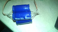
Well over a month in and finally some action I received the first 10 relay order Thursday and the 80 relay order form earlier this week Friday. So mental note. Fewer. Bigger. Orders. these coupled with the parts I already have and a quick trip to Radio Shack for some wire and quick and dirty switches has me poised to start building. The kids and I sat down to start work and 2 things became immediately clear 1 they wanted to know how it all worked in detail as bad as I did (good thing). 2 I have no idea how HP put those capacitors together the way he did because those leads leave no room for error with placement. Even with 2 sets of hands manning the iron and holding/positioning them just assembling 1 pack of 5 caps took the better part of 30 minutes.

Now I can be tenacious but I can smell wasted time in this not to mention the fact that I didn't much trust those craptastic connections so I grabbed a large perfboard I had laying around as a spare from my arduino LED cube build. here is the link for the perfboard. So the game plan for today is to desolder those caps then mount each pack in a corner of the perfboard and work with them there. The question then becomes weather to mount the whole clock circuit like that or to leave the relays off the board and mount them similarly to the rest of the computer. I think either way mounting the capacitors like this will neaten things up nicely which is always a good thing.
 |
| MY4 12DC coil 4PDT relay |
 |
| MY4 12DC coil 4PDT relay |
Let's take a look at the physical relay's themselves as they're kind of neat. As you can see in the pictures the relays aren't overly large they measure about an inch and a half high 3/4 of an inch wide and 1 inch long there are a total of 14 pins on the bottom which are blade style for insertion into a socket and have a hole in the blade for easy solder application should that be the case. In our case I will be doing all of the prototyping with sockets for ease of assembly and testing purposes as well as building a nice test assembly for quick and easy pre installation testing. In the pictures I've included my watch for scale as the pictures included in the HP computer materials was a little hard on scale for me. Internally the relay is quite a marvel of efficient packaging and even includes an LED on the coil to indicate when it is
energized which should add a whole other dimension of blinky blinky to our build. It does give the benefit of potentially removing some indicators throughout the build and my first thought is to rid myself of the indicators for the clock circuit overall.

 The following pictures are labeled to show the individual sections on each relay. the full images of these are in the google doc as well as a few others that I took and left unlabeled. Once the clock is put together I will likely post a short video of it in action.
At this point we haven't had time to get much built and with the sockets coming not much will likely get built for a few more days but the capacitor packs will be getting assembled and the wiring planned I will also be working on the test rig and will post a schematic of that soon. On orders I looked deeper into the power supplies used in the HP computer and he uses a now defunct Radio Shack model that was a 13.8VDC 10 A CB radio supply a brief search through amazon found similar here. The supply is at the heart of this build and Harry Porter used 2 of these 10 A supplies and I will be as well though for the time being I have only ordered 1 for testing and prototyping. Originally I had planned on using an old computer power supply for the ease of adding a 5V line for the memory chip circuit. That plan may still be put to use as I have an 850W Corsair supply that should supply more than enough power for the whole shebang.
I know today was a big deviation from the theory of late but the physical components are what this will ultimately be about and as much time will be spent on that as on the understanding and planning of the operation of this computer. Monday will likely cover in depth the operation of the finished clock circuit. Likely with lots of build pictures and hopefully a video of it running too.

No comments:
Post a Comment